Support mechanics are one of the most critical components in a linear motion design. They set the stage for the achievable performance in almost every metric. Options for components and methods range a broad span of capability and cost. Being able to identify key components while understanding the loading conditions and how they react with the support geometry will allow for an efficient and successful design. It’s important that the requirements of the system are well defined before putting pen to paper on the support mechanics design; this is discussed in “Navigating the Complexities of Motion Systems from Definition to Completion”. The following serves as an aid in load guidance design for linear motion control applications and identifies options to meet performance and cost targets in component selection and support mechanic geometry.
 Framing the System
Once the requirements of the system are defined, the natural progression of the design moves to the support mechanism of the axis directly coupled to the load. Starting at the axis closest to the load allows for accurate design of subsequent axis by including the weight of the components used. The forces on the axis can be calculated based on the motion profile and load definition of the system. It’s critical to include moment loading both from offset loads that will vary based on axis orientation as well as acceleration parameters of the motion profile. The example shown in Figure 1 is a basic horizontal axis with an offset load. For simplicity the mounting plate is considered rigid, and the load is drawn as a sphere with uniform density.
 |
Figure 1: Simple Offset Load for Horizontal Axis
|
Evaluating the static load condition of the axis starts with a free body diagram as outlined in Figure 2. For a static condition, the sum of the moments about point O (shown in Figure 2 as a red dot) will equal 0 as will the sum of the forces in the system. With the static conditions defined, equations 1 and 2 are derived from the free body diagram. The unknown forces are F1 and F2. Solving for equations 1 and 2 results in equations 3 and 4 which define forces F1 and F2 relative to force F. With F1 and F2 defined the friction force contribution for the static loading in this axis can be determined by the product of the coefficient of friction (COF) of the guide mechanism and the normal force to the guide mechanism (this will be determined by specific guide geometry). This example shows a factor of 3 increase in friction force by the static loading due to the overhung load and illustrates the importance of moment load evaluation in the design.
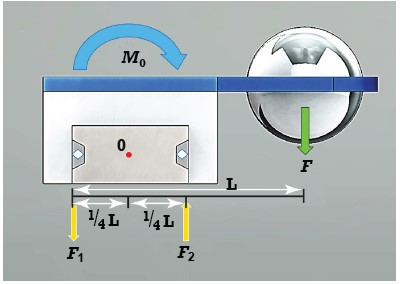 |
Figure 2: Free Body Diagram of Static Load
|
In addition to the static load there are dynamic forces from the acceleration of the motion profile that will attribute to moment loading and increase drag on the system. The static load condition of the single axis shown in figure 1 in a horizontal orientation will result in a roll moment as shown above, but once motion is introduced and acceleration and deceleration is considered a pitch moment and yaw moment will also be present. These will add to the overall drag in the system, and the required power to drive the load. Pitch, roll, and yaw moments are defined in Figure 3.
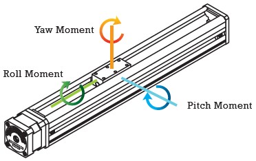 |
Figure 3: Moment Load Conditions
|
Implementing a Secondary Support Axis
It is not uncommon for moment loads to lead to the decision to add a secondary support mechanism in an axis of motion. This secondary support can be driven or passive. Evaluating the interaction between the primary and secondary support is also critical as a secondary axis can just as easily cause more problems than it solves if it is not implemented properly. The typical failure mode of a poorly designed secondary support axis is binding. Consider the axis in Figure 4. There is likely a restriction in the space envelope that requires the support mechanism to be setback from the load resulting in a large moment load on the guide. This may be addressed by using a large guide mechanism, changing to a different guide technology, adding a secondary guide for the axis of motion, or by a system redesign that changes the spatial constraints. Adding a secondary support is common practice and may be the best option.
 |
Figure 4: Overhung Load with Large Moment Arm
|
There are unique challenges when adding a driven or passive axis. A secondary passive axis will need to be low drag to avoid causing a large moment load on the first axis. Adding a secondary driven axis will require precise control of each axis to avoid binding. The dual guide axis in figure 5 is constructed of two plain bearing guide mechanisms with wear compensation to keep minimal clearances between the rails and the carriages. Rail X is driven and X’ is passive. The yaw moment acting on the X carriage has three sources; drag from the wear compensation of the X’ carriage, drag from the X’ carriage supporting a portion of the load, and the acceleration force of the load. The drag from the wear compensation mechanism is defined as 1 lb. The wear compensation method is undefined and as such the safe assumption is that the drag from supporting the load will be in addition to the drag of the wear compensation mechanism. For simplicity, the interface between the rail and the carriage is defined as perpendicular to the top and side surfaces of the carriage.
It is reasonable for a plain bearing slide to have a COF of 0.15. If the load is defined as 12 lbs and is equally supported between X and X’ the drag on each carriage from supporting the load is 0.9 lbs. The acceleration and deceleration ramps are defined as 0.5 g. The yaw moment acting on the carriage of X is 117.6 in-lbs; 45.6 in-lbs from the drag of carriage X’, and 72 in-lbs from the acceleration of the load as demonstrated in equation 5. The total pitch moment is relatively low in comparison at 6 in-lbs as demonstrated by equation 6. This load is equally shared between X and X’ and as a result each carriage will have a 3 in-lbs pitch moment. The roll moment on the carriage of X has now been compensated for by the carriage of X’.
 |
Figure 5: X and X’ support
|
| |
 |
| |
Yaw Moment = (6 lbs x 12 in) + (1.9 lbs x 24 in) = 117.6 in-lbs
Yaw Moment = Force x Perpendicular Distance to Load
Pitch Moment = Force x Perpendicular Distance to Load Eq (5)
Pitch Moment = (6 lbs x 1 in) = 6 in-lbs Eq (6)
|
The Effects of Moment Loads to System Drag
Evaluating the loads will help to define the magnitude of the drag on the X carriage which is an area of focus because all power transmission occurs through this axis. A diagram of the forces acting on the X axis carriage is shown in Figure 6.
The force resisting motion includes friction forces of the carriage as well as acceleration forces of the load and support mechanics. The total yaw moment of 117.6 in-lbs does not include acceleration of the support arm which has been idealized as 0 mass, but in application would have some contribution as well. The normal force of the load will be 6 lbs; half the weight of the load because it is equally support by X and X’. The pitch moment has been calculated as 3 in-lbs (6 in-lbs split between X and X’). The interaction of the carriage to the rail will help define the “force resisting motion”. To better understand this interaction the forces acting in each plane are identified and evaluated at the carriage.
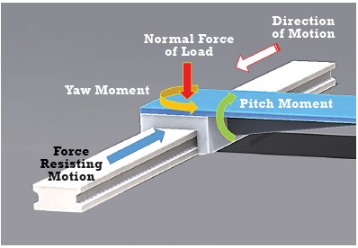 |
Figure 6: Forces Acting on X Axis Carriage
|
The forces acting on the X axis carriage in the top plain include the yaw moment, and the forces resisting motion. The interaction between the rail and the carriage will produce two additional forces F1, and F2 to counteract the yaw moment as shown in Figure 7. The forces F1, and F2 are 39.2 lbs each as shown in equation 7, and will contribute to the forces resisting motion as their magnitude is directly proportional to the frictional force. The forces acting on the carriage in the side plane include the 6 lbs load, and the pitch moment as shown in Figure 8. Similar to the top plane evaluation there are reaction forces between the carriage and the rail in the side plane as well.
These forces are identified as F3 and F4 and have magnitudes of 2 lbs and 4 lbs respectively as shown in equation 8. Due to the X’ axis support there is no additional loading witnessed in the front plane of the X axis carriage. If this were a single support axis as shown in Figure 2 there would have been a roll moment with reaction forces shown in the front plane in Figure 9.
 |
Figure 7: Carriage Load Evaluation – Top Plane
|
| |
Σ MO = 0 = 117.6 in-lbs – F1 x 1.5 in – F2 x 1.5 in
117.6 in-lbs = F1 x 1.5 in + F2 x 1.5 in
Σ FX = 0 = F1 – F2
F1 = F2 = 39.2 lbs Eq (7) |
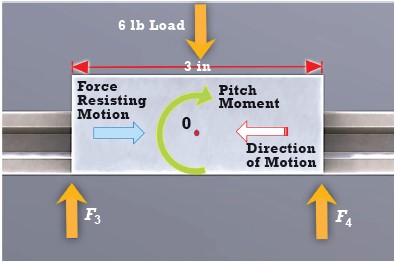 |
Figure 8: Carriage Load Evaluation – Side Plane
|
| |
Σ FX = 0 =
3 in-lbs = F4 x 1.5 in – F3 x 1.5 in
Σ Fy = 0 = F3 + F4 – 6 lbs
F4 = 6 lbs – F3
3 in-lbs = (6 lbs – F3) x 1.5 in – F3 x 1.5 in
F4 = 4 lbs
F3 = 2 lbs
3 in-lbs + F3 x 1.5 in – F4 x 1.5 in – 0 in x 3 lbs Eq (8) |
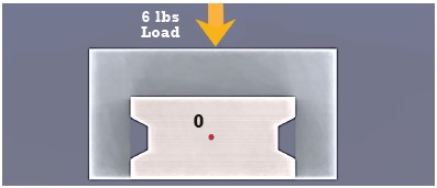 |
Figure 9: Carriage Load Evaluation – Front Plane
|
The drag forces of the X axis carriage can be calculated based on the carriage evaluation discussed, the rail geometry, and the COF between the carriage and the rail. It is reasonable for a plain sliding bearing assembly to have a COF of 0.15. For simplicity, the interface between the contact surface rail and carriage is defined as perpendicular to forces F1 through F4. With these assumptions the additional friction forces from the yaw and pitch moment load for the X axis carriage is 12.66 lbs. The total force resisting motion will also include the 6lbs to accelerate the 12 lb load at 0.5 g, and 2 lbs of drag from the X and X’ carriage preload. The drag on the system due to the configuration is relatively large and results in poor system efficiency. This idealized evaluation does not consider deflection of the components which can also add drag. For example, if the support arm to the X’ carriage deflects during acceleration the yaw moment on the X carriage will increase due to the additional drag on the X’ carriage (inducing a yaw moment in the X’ axis). The same result can also be caused by a deflection of the X carriage due to the 117.6 in-lb yaw moment.
Compensating for Manufacturing Tolerances
The evaluation does not consider misalignment of the two axes which will need to be reviewed based on tolerance stack up of the design. The axis may be over constrained because the carriages on X and X’ were both defined with 0 clearance in the X, Y, Z planes. Manufacturing tolerances of the rails, and their assembly will cause some degree of variation in their distance related to each other in each of these planes. If there is enough compliance in the carriage, or if mounting considerations are taken to allow for a degree of freedom this may be acceptable. One method of introducing a degree of freedom in the mounting scheme is to slot the mounting plate and secure it to the X’ carriage with shoulder bolts as shown in figure 10. With the orientation of the slot shown there is minimal axial play, and the path of motion is defined by the X axis allowing the load carrying member to float perpendicular to the X’ axis.
 |
Figure 10: Adding a Degree of Freedom
|
Improving Support System Efficiency
There are several methods to improve the efficiency of the system by reducing drag. An obvious solution is to reduce the friction of the sliding components which can be achieved by substituting the plain bearing rail configuration with a rolling element configuration such as a ball rail. The COF of a ball rail is typically 0.001 which greatly reduces the drag forces on the system. Another method is to reduce the moment loads acting on the carriages. In the example axis the largest contribution to moment loading has been yaw. There are two basic changes that will reduce the yaw moment acting on the X axis while still using a passive X’ carriage. The first change is to replace the X’ axis with a free sliding member such as a general purpose guide rod. These typically have no measurable drag and some degree of clearance between the rail and the bushing. They can also have a custom fit that will allow for a degree of freedom perpendicular to the rail as was discussed to avoid binding. The yaw moment of the X carriage in this case is reduced by 24 in-lbs (the result of the 1 lb drag from the wear compensating carriage of X’). The second change is to add a secondary passive carriage on the X axis. The effect of the second carriage on the X axis will be proportional to the allowable distance from the first carriage. One limiting factor in this configuration is the available space because any addition directly increases the length of the axis to keep the same stroke. For this example adding an additional carriage 3 inches apart from the original carriage on the X axis and replacing the X’ axis with a guide rod assembly reduces the drag caused by moment loading on the carriage of X to 5.58 lbs, down from 12.66 lbs. The assumptions with this arrangement are that the X
axis carriages take up the entire yaw moment due to their spacing, the load on each X axis carriage is evenly distributed and therefore can be applied at the center of each, and the mounting configuration allows for each carriage to take the yaw moment as a side load. The resulting support mechanism is shown in Figure 11.
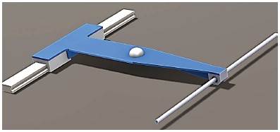 |
Figure 11: Support with Additional X carriage and Guide Rod for X’ Axis
|
The biggest reduction of the yaw moment in this example will be to drive both the X and the X’ axis. In a properly designed and idealized dual axis configuration where both axes are driven there will be no yaw, or roll moment on the X and X’ carriages. Care must be taken in coordinating the motion between both to avoid binding. This can be achieved by a mechanical coupling between each drive mechanism such as a drive shaft or drive belt, or by high level controls of individual motors driving each axis. If using a mechanical coupling the device will need to be sized and implemented properly as belts can stretch and vary with loads, and rods will have torsional deflection proportional to the shaft length, and torsional load. If driving each axis individually the control scheme should allow for coordinated motion between each axis. If possible, the use of linear encoders as the feedback device is recommended as it gives more accurate positional information than rotary encoders because it’s providing information at the carriage. Rotary encoders are also a good choice, but they do not account for compliance in couplings and other mechanical power transmission devices that may have built up inaccuracies due to dynamic deflections and manufacturing tolerances. In coordinated motion it is common to have each axis error out and safely stop if either one exceeds a defined position error to avoid binding or a crash. While driving motors independently without coordinated motion is possible it can be problematic as a single axis may fail, or fall behind causing the system to rack and has the potential to cause damage to both the axes of linear motion, and other components in the system.
A large moment load does not necessarily mean a large increase in drag. The support technology will help define the actual drag force on the system. Generally plain bearing technology has a COF in the realm of 0.1 to 0.2, a rolling element option typically has a COF of 0.001, and a fluid option, such as an air bearing has a COF as low as 0.00001. In addition to less drag, low friction guides have the ability to improve the precision of the system because lower friction allows for smaller incremental moves. There are many factors to consider when selecting the technology for the system guidance that will not be discussed in detail here. A comparison of some performance metric generalities between plain bearing, rolling element, and fluid based support mechanisms is shown in Table 1.
| Table 1: Support Mechanics Quick Reference Table |

|
A Dynamic Carry to the Finish
All linear motion systems require dynamic load support that in a given axis allows for a single degree of freedom while fixing or limiting motion in all other directions. The support and guidance of the load is one of the most critical to function system considerations and there are many options to execute design both in component selection and system support geometry. Understanding how the guidance components react to the static and dynamic loads leads to a proper design allowing for efficient transmission of input power to the load. Although there were several assumptions made in the example evaluation, component manufactures in most cases are willing to share details of their guidance systems to allow engineers to completely define the guidance of a system. Load guidance is one of the areas of system design where a high degree of creativity and strong analytical skills can carry a design engineer through a web of options to a truly unique solution meeting the system needs for function, cost, longevity, and performance.
Click here to download PDF version.